| Last Updated: December 8, 2016 |
| Status: |
Models and Serial Numbers: |
Date of Issue: |
Reference Number: |
Description: |
| REQUIRED |
All Turbo Engine Kits and Turbo Upgrade Kits shipped prior to April 2017 |
06.23.17 |
ACV-SB-062317 |
AeroVee Turbo Oil Pump O-Ring Replacement
The -6AN Fitting Adapter (part number 991955ERL or ACV-T05-44, as supplied), installed in the right hand port of the Secondary Oil Pump, must have the
supplied O-Ring removed and replaced by a crush washer. Failure to remove
the O-ring may result in the O-ring entering the oil system, resulting in
loss of engine lubrication and possible engine seizure.
The linked page from the Turbo AeroVee Assembly Manual highlights the crush
washer installation. Download: ACV-SB-062317.pdf
AeroConversions will provide a crush washer upon request. Please email
tech@aeroconversions.com and reference "ACV-SB-062317 crush washer, part
number ACV-T05-45." Include your mailing address in your request and the
engine's serial number.
A crush washer of the following specifications may be used in lieu of
ACV-T05-45:
- Aluminum Sealing (Crush) Washer
- M16
- 16.2mm I.D. (approx.)
- 19.9mm O.D. (approx.)
- 1.3 to 1.7mm thick
Completion of this SB must be noted in your engine logbook. |
| UPDATE: SUGGESTED |
ALL AeroVee Turbo Engines |
03.05.18 |
ACV-SB-091616-1B |
AeroVee Turbo Coking - New Cooling System
A dedicated turbo cooling system is now available, allowing AeroVee Turbo pilots to keep their turbochargers in top condition by actively cooling the turbo when it matters most: after engine shutdown.
The AeroVee Turbo Cooling System weighs less-than 5 lbs. including coolant, and is thermostatically controlled. You can shut the aircraft master switch off and leave the aircraft, and the cooling system will automatically shut-off when temperatures in the turbocharger's bearing block are reduced to specified levels, which typically takes about 20 minutes with under 0.1 volt drop in battery charge.
The system is currently offered as a Bill of Materials so that customers can source at the lowest cost, and vary individual components to best fit their individual installations in a variety of airframe models. Sonex Aircraft sells the custom coolant catch can for the system.
Get more details and subscribe to the project mailing list for automatic updates from the Hornets' Nest R&D Web Site. |
| REQUIRED |
ALL AeroVee Turbo Engines |
09.16.16 (Rev NC)
10.14.16 (Rev A)
12.08.16 (Rev B) |
ACV-SB-091616-1B |
AeroVee Turbo Coking - Revision B
Sonex Aircraft has identified reliability issues in factory and customer AeroVee Turbo installations related to the possible coking of oil and/or accumulation of rust deposits on internal turbo components which may cause the turbo impeller to no-longer spin freely. In this situation, the engine may fail to provide any boosted power, which will result in limited RPM with AeroVee Turbo propellers.
The following items are mandatory for all AeroVee Turbo Installations until further notice or modification:
1. Oil Selection: Sonex Aircraft is investigating several semi-synthetic oils that may be more suitable for AeroVee Turbo application. Conventional oils should not be used with the AeroVee Turbo, specifically, Valvoline VR1 is no longer approved by Sonex, LLC for the AeroVee Turbo. Further, new service bulletin ACV-SB-091616-2 states that Full-Synthetic oils may no longer be used in any AeroVee Engine due to incompatibilities with leaded aviation fuel and Full-Synthetic oils. Specifically, Valvoline VR-1, 20w50 synthetic and Mobil 1, 15W-50, are no longer approved. Semi-synthetic oils with high zinc and phosphorus content should be used. Sonex Aircraft will provide updated specifications with specific recommendations for AeroVee Turbo Approved Oils at a later date, following more oil testing. Our recommendations at this time, as recommend by our turbocharger supplier:
- Brad Penn semi-synthetic Penn-Grade 1 Racing 20w50
2. Turbo Cooling: The AeroVee Turbo should be run at-idle power for a minimum of 3 minutes prior to engine shut-down. Note: previous versions of the AeroVee Turbo manual did not specify cool-down time at idle power.
3. Run-Up and Takeoff Roll Power: Prior to each flight, a high-power run-up must be conducted to verify normal boost pressures and engine RPM. Run-ups should be conducted at full throttle if static braking conditions and performance allow. Do not attempt flight if boost pressures and/or RPM are abnormal during run-up. Engine power should be closely monitored early in the takeoff roll. The takeoff should be immediately aborted if the engine does not develop full takeoff power (40” MAP).
4. Turbo Installation in Tailwheel Aircraft: Owners of tailwheel aircraft must reclock their turbochargers so that the oil drain galley is oriented vertically (perpendicular to the ground) when the aircraft is sitting on it’s gear (3-point attitude). This will reduce oil pooling in the turbocharger’s bearing block after engine shutdown.
5. Additional Oil Filter: A spin-on oil filter must be added to the turbo oil feed line between the engine and turbo oil inlet. Recommended remote oil filter mount: Derale brand, part number 25044. Sources:
Recommended oil filter: FRAM PH8172 or equivalent.
Remote oil filter mount may be attached to firewall or engine mount tubes, based on available space, typically on passenger side of engine compartment. The existing permanent oil filter in the engine’s oil sump should remain installed. Braided hose should be used with 1/4” NPT AN fittings from engine to oil filter mount, and from oil filter mount to turbo. Download: ACV-SB-091616-1A_Oil_Filter_Install.jpg
A hose clamp secured to the bottom of the oil filter canister should be used to safety wire the canister to the oil filter mount. Download: ACV-SB-091616-1A_Oil_Filter_Install-Safety_Wire.jpg
6. Trimming Oil Drain Fitting: The turbocharger oil drain fitting must be trimmed flush with the top surface of the ACV-T05-46 Turbo Oil Drain Plate. Download: ACV-SB-091616-1A_Turbo_Oil_Drain_Fitting_Trim.jpg
Optional part ACV-T05-73 Machined Turbo Drain Sump may be used in-place of the existing ACV-T05-46 Turbo Drain Plate.* Download: ACV-T05-73_Machined_Turbo_Drain_Sump_Installed.jpg
7. Turbo Shroud: New assembly ACV-T05-72 Stainless Turbo Shroud must be installed in-place of the ACV-T05-49 Turbo Blanket, which is no-longer to be used on AeroVee Turbo engines.* Download: ACV-T05-72_Stainless_Turbo_Shroud_Installed.jpg
Alternate Cause Theory and Optional Service Procedures:
Since the publication of Revision A of this service bulletin, no new turbocharger seizures have occurred in the factory or customer AeroVee Turbo fleet, and Sonex Aircraft has therefore not had an opportunity to analyze a seized turbine shaft “piston ring” type seal for possible rust deposits. Tornado Alley Turbo Inc. service bulletin TAT SI15-02 ( http://www.taturbo.com/TAT%20SI15-02%20frozen%20turbos.pdf ) and related Continental Motors service bulletin M71-21 ( http://www.tcmlink.com/pdf2/M71-21.pdf ) present a plausible theory regarding the cause of AeroVee Turbo turbine shaft ring seal seizures that is alternate to coked oil deposits as a cause of the seizures. These service bulletins state that rust deposits in low time (under 100 hours) turbochargers are the cause of turbine shaft ring seal seizures that have occurred in the applicable type-certified and STC turbocharger installations. Per the Tornado Alley service bulletin description:
"This condition occurs when the turbocharger is new or newly overhauled and heat and normal operation have not yet formed a protective layer on the internal parts that protects them against oxidation.
During periods of prolonged inactivity (typically several days to weeks, and more frequently in humid weather) these deposits from oxidation may cause a restriction so that on initial engine start up, the turbocharger does not spin up."
All AeroVee Turbo seizures to-date have occurred on turbochargers with less-than 100 hours, and prolonged periods of inactivity are common in VFR recreational aircraft such as the Sonex line of aircraft due to inclement weather and/or personal schedules. Therefore, Sonex Aircraft strongly suspects this alternate cause as a possible major factor in AeroVee Turbo seizures.
The above-referenced service bulletins prescribe troubleshooting remedies involving penetrating oil to free-up seized turbochargers that may be followed by AeroVee Turbo customers.
Note, however, that the Continental Motors service bulletin states:
"Units which are binding after long time service are coked internally and must be removed for cleaning or replacement."
Additionally, turbocharger STC vendor RAM Aircraft publishes an annual solvent flush procedure as preventative maintenance that may be utilized by AeroVee Turbo owners ( http://www.ramaircraft.com/Maintenance-Tips/Save-A-Turbo.htm ). Note that the turbo oil supply and oil drain lines must be disconnected to isolate the turbo from the engine’s oil system during this procedure, and that a thorough mineral spirits flush (may require several ounces of mineral spirits) must be made to remove any loose particles from the turbocharger before reconnection to the engine’s oil system. Sonex Aircraft has used the Berryman B12 Chemtool solvent prescribed in the RAM Aircraft flush procedure to free a seized turbo before return to the turbo manufacturer for overhaul, and found the solvent to be effective.
*New Parts from Sonex Aircraft:
- ACV-T05-73 Machined Turbo Drain Sump is now available to existing AeroVee Turbo customers for $39.99** and will be included as a mandatory part in all future AeroVee Turbo kits. Click to Order
- ACV-T05-72 Stainless AeroVee Turbo Shroud Assembly is available to existing AeroVee Turbo customers at reduced cost of $11.64** and will be included in all future AeroVee Turbo kits. Click to Order
** Prices current as-of date of service bulletin release and are subject to change without notice.
Service Bulletin Revision Log:
- Revision A (10.14.16):
- Added: Item 5. Additional Oil Filter
- Added: Item 6. Trimming Oil Drain Fitting
- Revision B (12.18.16):
- Added: Item 6, Paragraph 2: Optional Part ACV-T05-73
- Added: Item 7. Turbo Shroud
- Added: Alternate Cause Theory and Optional Service Procedures
- Added: *New Parts from Sonex Aircraft
- Consolidated all revisions into single contiguous document
- Added: Service Bulletin Revision Log
Any questions should be directed to AeroConversions Technical Support staff at: tech@aeroconversions.com |
| REQUIRED |
ALL AeroVee Engines (non-Turbo) |
09.16.16 |
ACV-SB-091616-2A |
Approved Oils
Revision A: Updated 02/26/2020 with specific oil brand recommendations
Approved Oil Specifications for AeroVee Engines have changed in-light of current oil industry research with modern oil formulations that prohibit the use of Full-Synthetic oils with leaded aviation fuel. Full-Synthetic oils listed as approved in previous revisions of AeroVee documentation (Valvoline VR-1, 20w50, synthetic and Mobil 1, 15W-50) are no longer approved. Note that Synthetic-Blend oils may still be used.
Approved Break-In Oils Are:
- Valvoline VR-1, 20w50, non-synthetic
- Brad Penn Penn-Grade 1 Racing 20w50 (Partially Synthetic: Recommended for AeroVee Turbo)
Approved Post-Break-in Oils Are:
- Valvoline VR-1, 20w50, non-synthetic
- Brad Penn Penn-Grade 1 Racing 20w50 (Partially Synthetic: Recommended for AeroVee Turbo)
Any questions should be directed to AeroConversions Technical Support staff at: tech@aeroconversions.com |
| REQUIRED |
AeroVee engines and replacement cases shipped between November 1st, 2015 and May 1st, 2016. Your engine’s packing list and invoice are dated. Note: Sonex Aircraft has attempted to contact, via email, each of the customers we believe may have received a defective case. |
05.04.16 |
ACV-SB-050416 |
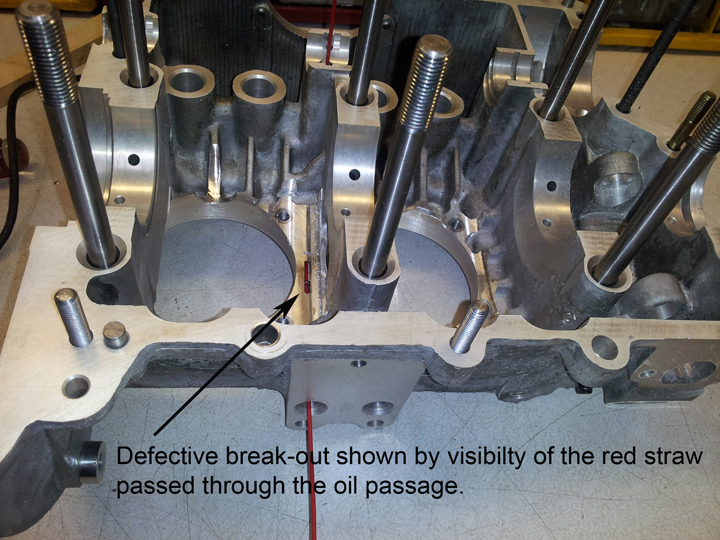
Oil Passage “Break Out” from Improper Machining
Between November 1st, 2015 and May 1st, 2016 Sonex Aircraft delivered engine cases that may have a machining error from our supplier.
If you took delivery of a new AeroVee engine case during this period perform one these mandatory inspections:
Unassembled engine:
Inspect the oil passage that feeds the center cam bearing for "break-out" between the base of the cylinders. This is shown in the accompanying photo by the appearance of the red straw. This break-out of the oil passage is the defect. See image illustrating defect
Assembled Engine:
If you have already run your engine and have proper oil pressure it is highly unlikely you received a case impacted by the machining error. The break-out of the oil passage would result in the loss of oil pressure. However, the only way to know for sure is to perform the inspection described below.
To inspect an assembled engine, remove a cylinder head and one rear cylinder. With the cylinder removed you can inspect the affected area with a mirror.
If your engine is impacted by this machining error please contact us at tech@sonexaircraft.com. |
| RESCINDED |
AeroVee Engines Shipped between June 2014 and December 2014 (approx S/N range: 760 – 810) |
05.14.15 - Rescinded 06.19.15 |
ACV-SB-051415 |
Rescinded: Defective Primary Ignition Modules
Service Bulletin Rescinded for Defective Primary Ignition Modules (Magnatrons) - DPST ignition switch would not turn modules off. Multimeter test prescribed in original service bulletin proved inconclusive. Service issue existed in very isolated cases, and improper Installation is suspected in some.
|
|
REQUIRED
|
ALL AeroVee Engines
|
06.17.14
|
ACV-SB-061714
|
ACV-Z01-36 (3/4” long) Flat Head Socket Cap Screw Replacement
Sonex Aircraft requires the immediate replacement of all ACV-Z01-36 (3/4” long) Flat Head Socket Cap Screws that hold the Trigger Shaft Assembly (ACV-F01-24) to the Flywheel with ACV-Z01-81 (7/8” long) Flat Head Socket Cap Screws. The ACV-Z01-81 screws provide added thread engagement to help prevent these screws from potentially backing out. Applying Locktite Primer and 242 Threadlocker, and using the proper tightening procedure on these cap screws are also extremely important.
See the following AeroVee Installation Manual Page that references this hardware and details the proper assembly, Download: ACV-SB-061714_Flywheel_Cap_Screws.pdf
All AeroVee Engines sold since late 2012 include the longer ACV-Z01-81 Cap Screws.
Any AeroVee Engines sold before late 2012 that have the ACV-Z01-36 (3/4” long) Flat Head Socket Cap Screws on the packing list and/or installed can obtain new ACV-Z01-81 (7/8” long) Cap Screws at no charge. Please contact the Sonex Aircraft orders department to initiate this order, reference ACV-SB-061714 and include part numbers ACV-Z01-81, Qty 4: orders@sonexaircraft.com
|
| OPTIONAL |
ALL AeroVee Engines with Nikasil Cylinder Option |
05.21.13 |
ACV-SB-052113 |
Nikasil Cylinder Piston Retaining Clips
All AeroVee Nikasil Cylinder Owners should be advised that Sonex has received two reports of damage to the Nikasil Cylinder barrel walls from the Piston Clips coming out of the keeper groove.
We believe this damage has two main factors:
- If the clips are not installed properly, they may not be sitting in the groove and could exit the side of the piston and cause damage. A distinctive "click" should be heard when the two sides of the clip are released. It is imperative that you confirm full engagement of each clip in its groove. Sonex also highly recommends the purchase of a "c-clip" pliers or equivalent to accomplish the installation of these clips.
- The clips supplied to Sonex from the Nikasil Piston vendor do not fit as tightly as other clips we have sourced. We have replaced all of the clips in the Nikasil Cylinder sets with the following item and stock number from AirCooled.net: 4590-10.
Sonex Aircraft highly recommends that at the next Annual inspection the current piston retaining clips be thoroughly inspected or replaced with the Part Number above.
All AeroVee Engine Packing Lists with Nikasil Cylinders dated 5.8.13 or newer include the new clips.
|
| REQUIRED |
ALL AeroVee Engines |
03.13.12
Rev A: 03.23.12 |
ACV-SB-031312-A |
Alternator Stator Cap Screws
All AeroVee Owners must immediately check the 4 cap screws that attach the Alternator Stator (P/N ACV-A01-15) to the Alternator Mount Plate (P/N ACV-A01-03).
If 8-32 thread x ½ long Socket Head Cap Screws (P/N ACV-Z01-12) are installed, these must immediately be replaced by a patched 8-32 thread x 5/8 long Socket Head Cap Screws (P/N ACV-Z01-76). McMaster-Carr P/N 91205A195 or equivalent.
All AeroVee Engines shipped since 1.1.2012 include the new cap screws along with most from 2011. If your AeroVee Engine Packing List contains ACV-Z01-76, you have the 5/8 length screws.
Attached is Page 37 from the AeroVee Assembly and Maintenance Manual, which includes the installation instructions for this Assembly. Download: AeroVeeAssemblyManual_Page37.pdf
Additional Information (added to Revision A on 03.23.12):
- This service notice does not apply to any AeroVee Engines with the 10 AMP Stator Alternator.
- The reason for this service notice is to eliminate the possibility of severe damage to the flywheel, secondary ignition and/or alternator if the hardware is not tightened properly or Loctite is not used. To date there has been one incident of a flywheel being destroyed where the backing out of these screws is a possible cause.
- There is some variation in the depth of the hole and threads in the ACV-A01-13 Alternator Mount Plate (ACV-A01-03 Mount Plate Assembly). First install the ACV-Z01-76 screws and ensure the stator is fastened tightly. If the alternator stator is not tightly attached to the plate, the screws may be bottoming out in the mount plate. Modify the Mount Plate per the attached control print. Download: ACV-A01-13_RevA_MOD_Alt_Mount_Plate.pdf
|
| REQUIRED |
AeroVee Engines shipped between 3/1/2010 and 8/19/2011 |
08.19.11 |
ACV-PRN-081911 |
Kit Hardware Mis-Labeled
AeroConversions discovered today (Friday 8.19.11) that incorrect hardware
had been labeled as ACV-Z01-36 Flat Head Cap Screws and shipped to
customers. P/N ACV-Z01-36 is a 1/4-28 thread x .75" long Flat Head Socket
Cap Screw (Fine Thread). This Part Replacement Notice impacts AeroVee
Engines shipped between March 2010 and today (Friday August 19, 2011).
The entire stock labeled on our shelves were actually 1/4-20 thread x.75"
long Flat Head Socket Cap Screws (Coarse Thread).
These screws secure the secondary ignition trigger shaft assembly to the
flywheel and are installed by the builder, not pre-assembled by AeroConversions.
The ACV-F01-11 steel center fitting in to which these screws thread is
drilled and tapped for a 1/4-28. A coarse thread socket cap screw can be
installed and will give the incorrect impression that it's provided a tight
fit. The resulting joint using this hardware is not acceptable and must be
repaired.
All AeroVee Customers who received their engines since March 2010 and have
not assembled their engines must immediately check your ACV-Z01-36 Screws
and verify they are the correct 1/4-28 thread. If found to be the incorrect
thread, please contact us immediately at techsupport@aeroconversions.com and we will
send you the correct hardware at no charge.
If the ACV-Z01-36 hardware has already been installed, the alternator cover
plate should be removed and one of these 4 screws should be removed and
verified for proper thread. If they are found to be coarse thread, then a
re-tapping to 1/4-28 can be attempted. If this does not succeed, the
flywheel should be removed and the 4 mount holes should be up-drilled and
tapped for a 5/16-24 x 3/4" length thread flush head cap screw. Please refer
to your AeroVee Assembly Manual for the proper installation instructions for
this hardware. |
| REQUIRED |
ALL AeroVee Engines |
10.30.09 |
ACV-SB-103009 |
AeroVee Oil Specifications
This update to the AeroVee Assembly manual details the
approved oils for the AeroVee engine. Information originally contained in this service bulletin is superceded by service bulletin ACV-SB-091616-2 (listed above). |
| OPTIONAL |
ALL AeroVee Engines |
08.14.09 |
ACV-SB-081409 |
Optional AeroVee Crank Case Oil Restrictor Plug Removal
These instructions below detail the removal of a restrictor plug installed in the oil galley near the #1 (front) bearing, and its replacement with a threaded plug: CaseRestrictorPlugRemoval.pdf
AeroConversions has never found evidence that the solid plug restricts oil flow, but offers these instructions for those who feel the oil flow to the #1 bearing may be impeded. Having accomplished this procedure recently on 3 of the factory demonstrator engines and seeing no negative consequences, AeroConversions has decided to remove this restrictor plug from all new AeroVee 2.1 Engines (delivered on or after August 14, 2009).
Note: If your oil pressure drops below the published operating limits after performing this operation you may need to install an oil pressure adjuster in the rear oil pressure relief port to maintain the minimum oil pressure of between 40 and 50 psi at 3000 rpm. |
| REQUIRED |
ALL AeroVee Engines |
05.29.09 |
ACV-SB-052509 |
AeroVee Service Check and Possible Repair: Oil Pressure
A few instances of low oil pressure have been reported by AeroVee Pilots. AeroVee
Engines must be operated with an oil pressure between 40 and 50 psi at 3000 rpm.
Running with low oil pressure can lead to a catastrophic engine failure.
If you are experiencing low oil pressure, first try placing a shim under the oil pressure
relief plug at the flywheel end of the engine. If this does not correct the problem, remove
the plug, spring, and plunger and check the condition of the plunger seat in the case.
Below are two images: one showing what the correctly machined plunger seat area should
look like and one that is incorrect. If you are not flying yet, inspect this area of your case
and ensure you have the correctly machined plunger seat.
Oil_Relief_Galley_Correct.jpg
Oil_Relief_Galley_Incorrect.jpg
If you find that you do not have a correctly machined pressure relief port seat in your case, please contact Sonex Aircraft Technical department at: techsupport@aeroconversions.com Sonex Aircraft can provide a loaner tool, part number ACV-Relief-Port-Tool, for performing an effective field repair of the port’s seat. |
| OPTIONAL |
ALL AeroVee 2.1 Engines |
05.11.09 |
ACV-SB-051109A |
AeroVee Service Check: #1 Bearing Chamfer
A few AeroVee 2.1 Owners have reported that the #1 Bearing feels a little “sticky” when it’s placed on the crankshaft and rotated next to the counterweight. See attached image: AeroVee_BearingMod_A.jpg
This “sticky” feel on the bearing is due to the radius that was added between the crankshaft counterweight and bearing race on the custom AeroVee 2.1 Crankshaft. Perform the check shown in the picture above. If you observe this “sticky” feel it can be easily eliminated by creating a small chamfer on the inside edge of the bearing. Remove the bearing and chamfer the edge facing the counterweight. This can either be accomplished using a fine, half-round file or a Scotch Brite Wheel shown in the attached image. Thoroughly clean the bearing before final installation. Only a small amount of chamfer is required to eliminate this issue. See attached images: AeroVee_BearingMod_B.jpg and AeroVee_BearingMod_C.jpg |
| OPTIONAL |
ALL AeroVee 2.1 Engines |
05.11.09 |
ACV-SB-051109 |
AeroVee Service Check: Crankshaft End Play
A few AeroVee 2.1 Owners have reported that there is only enough end play with the combination of the custom crankshaft and steel center fitting provided on the flywheel for a single shim.
We recommend that you perform the End Play Check detailed in the Crank Case Assembly Section of the AeroVee Assembly Manual immediately. Determine the amount of End Shim required for your particular Crankcase, Crankshaft, and Center Fitting combination. Ideally, there should be Qty 3 end shims used to reach the required 0.003” to 0.006” of end play.
Sonex has created an ACV-F01-11 Rev A to increase the amount of end play for those that require it. A part exchange of the new part is available to AeroVee Customers at no charge. If you find that you do not have sufficient end play, please contact the Sonex Tech Department for an RMA number and to arrange for this part exchange at: techsupport@aeroconversions.com
Note that the replacement ACV-F01-11 will be stamped with an “A” that will be visible on the Center Fitting when the flywheel is assembled. |
| REQUIRED |
ALL AeroVee
Engines. |
09.12.08 |
ACV-SB-091208 |
AeroVee Service Check: Secondary Ignition Trigger Magnet Size
If you have a red ACV-F01-21 Trigger Magnet Cap Assembly, check to ensure
the proper diameter trigger magnet is installed. Your trigger cap should look like the one on the right with a 1/4 inch diameter magnet. (This check
does not apply to the black trigger magnet caps).
See attached image: Trigger-Magnet.jpg
General AeroVee Assembly Practice:
Do NOT Install the Oil Breather Gasket w/louvers that comes as part of the
standard vw gasket set (ACV-P01-69 -or- ACV-P02-15).
See attached image: Oil_Breather_Gasket_DoNotUse.jpg
Do NOT place a chore-boy, steel-wool, or any other metal object into the
Breather plate assembly. Over time, this can break down and metal particles can work their way into the engine case. DO put a larger hump in your oil
breather tube so any oil that bubbles out of your case will drain back into the case rather than flow out the bottom of your airplane.
We also understand some engine builders have needed additional barrel shims
for their engines depending on what compression ratio they chose to set
their AeroVee Engine at. (7:1 CR requires more shims than 8:1 CR). It's
difficult to get all of the combinations covered in one standard package
without being wasteful. Sonex furnishes (and has only charged the customer
for) one set of 0.060" Head shims and one set of each of these barrel shims:
0.090, 0.060, and 0.040. Additional shims are available for purchase from
Sonex with the following part numbers to suit your particular needs:
ACV-P01-39 0.090 Barrel Shim Qty 4 $7.00/set
ACV-P01-40 0.040 Barrel Shim Qty 4 $6.00/set
ACV-P01-41 0.060 Barrel Shim Qty 4 $6.00/set
ACV-P01-92 0.060" thick- Copperhead Gasket Qty 4 $26.00/set |
| REQUIRED |
ALL AeroVee
Engines. |
10.30.07 |
ACV-SB-103007 |
General AeroVee Prop Hub Assembly/Removal Practice
Aeroconversions does not recommend installing the Prop Hub or any other shrink-fit components with a press without first cooling the crankshaft in a freezer and heating the installed components in an oven. The recommended assembly procedure is detailed in the AeroVee 2.0 Assembly Manual and AeroVee Assembly DVD. Attempting to press these components on cold can result in extremely high stresses in the nose end of the crankshaft. Any misalignment between the shrink-fit component and crankshaft may result in damage to both components and could result in stress cracking, a crooked prop hub, and a structurally inadequate shrink-fit joint.
All Printed AeroConversions Materials approving the method of cold press for this procedure must be updated by striking this out with a permanent marker.
All Crank Shaft Assemblies that have been accomplished using a cold press method must have their runout checked with a dial indicator per the following image: ACV-SN-101807_runout_check.jpg and the results submitted to AeroConversions by e-mail: techsupport@aeroconversions.com
All Assemblies accomplished using a cold press method must also be removed and checked thoroughly including a magnaflux process on all components to ensure stress cracks are not present.
Note: It is acceptable to press the prop hub on if it is within 1/8" of the final installation contacting the oil slinger. It is critically important that the crankshaft have proper support behind the front journal. Refer to
the following image showing this technique with proper support behind the front journal: ACV-SN-101807_journal_support.jpg |
| REQUIRED |
SERIAL NUMBERS AFFECTED:
0001-0332 |
6.27.05 |
ACV-SB-062705 |
Accessory Case/Flywheel Centering Check
We have found that a few of the Supplied Crank Cases (Old P/N 1274 New P/N ACV-P01-36) do not have the transmission locating/centering boss on the flywheel end of the case concentric with the crankshaft bore. This does not impact the operation or service of any of the AeroVee Parts. It can, however cause a slight mis-alignment between the AeroVee Accessory Case (x-mount P/N ACV-A01-01) and the center of the crankshaft. If this misalignment is more than 0.015 inches, the alternator stator can contact the magnet ring, causing, in extreme cases, the stator to be burned up.
The identification of this problem and the fix are both simple procedures: The following check is required BEFORE RUNNING YOUR ENGINE FOR THE FIRST TIME:
Step 1: Remove the Alternator Mount Plate and " Paint " the outer surface of each coil of the alternator stator (See Figure 1 and Figure 2) and inside of the magnet ring Blue (See Figure 3 and Figure 4) with a permanent blue Sharpie Marker.
Step 2: Reattach the stator mount plate assembly to the Accessory Case. (Reinsert as carefully as you can to keep the Blue Marker intact. Also remember that the magnets are strong! They will pull the alternator right out of your hand and can pinch your fingers).
Step 3: Remove one set of spark plugs and manually rotate the crankshaft (turn the engine over) 3 or 4 revolutions. A socket on the prop hub attach bolt works well to pull the engine through.
Step 4: Remove the stator mount plate assembly and inspect the blue paint on the stator and magnet ring. (Again use care to keep from scratching off the Blue Marker as you remove the stator). If the blue marker is intact on both the stator and magnet ring, your alignment is acceptable. If either the stator or magnet ring show signs of contact, proceed to Step 5.
Step 5: Remove material from the Alternator Stator using a belt sander or equivalent where the Blue Sharpie has been wiped from the Stator. (See Figure 5 and Figure 6) Repeat Steps 1 through 4 until no contact is evident. Note that this same procedure can be used on the primary ignition (magnetron units) by " painting " the trigger magnet on the flywheel to ensure no contact is occurring between the magnet and ignition module.
(list of all images for this Service Notice):
Painting the Stator- Figure 1
Painting the Stator- Figure 2
Painting the Magnet Ring- Figure 3
Painting the Magnet Ring- Figure 4
Removing Material from the Stator- Figure 5
Removing Material from the Stator- Figure 6 |
| REQUIRED |
SERIAL NUMBERS AFFECTED:
0101-0227 |
6.16.05 |
ACV-SB-061605 |
Proper Grounding Procedure
The red anodized surfaces of your AeroVee Engine Components act as an insulator. For the primary and secondary ignition coils to function properly, they must be grounded. In order to ensure their proper function, we highly recommend the installation of a ground wire to the body of each ignition unit. This ground should be routed directly to the engine crank case. Below are images of the areas to place a ground wire for the Primary and Secondary Ignitions (see images below):
AeroVee Primary Ignition Grounding
AeroVee Secondary Ignition Grounding
New Assembly Procedure for Flywheel:
The o-ring mounted in the steel center fitting of the flywheel has proven to be a challenge to install for some builders and has the potential to cause a problem by getting pinched in between the flywheel and back of the crankshaft. This can keep it from seating all the way and can cause the flywheel to turn off-center leading to potential ignition and alternator problems. We recommend removing the o-ring and applying a light coat of high-temp silicone sealant to the dowel pin area and a 1/8² diameter bead in the o-ring groove.(see image below):
Flywheel High-Temp Silicone Application
General Prop Hub Assembly/Removal Practice:
Do not use a propane torch or other flame to remove shrink-fit components under any circumstances. If you have used a torch on any of your shrink-fit components, they MUST be replaced immediately. The proper removal procedure for all of your shrink-fit components is to use a hydraulic press with no heat applied.
One other quick note on ongoing maintenance and supplemental materials for your AeroVee. There are some excellent reference materials available that we strongly urge all AeroVee builders to purchase, read, and add to your permanent reference library as supplements to the AeroVee Assembly Manual and DVD. These materials are available at most major bookstores and online from the major book sellers.
One book in particular has become the vw builder guru's primary reference book. This book is titled " How to Rebuild your Volkswagen Air-Cooled Engine " by Tom Wilson (1987). Any AeroVee Builder who reads this book cover-to-cover will be prepared for most any maintenance issue and will have a better working knowledge of the VW Engine from the inside out. |
| REQUIRED |
SERIAL NUMBERS AFFECTED:
0101-0188
0192-0193 |
8.19.04 |
ACV-SB-081904 |
Flywheel Assembly Service
This MANDATORY SERVICE BULLETIN enhances the durability and reliability of the AeroVee Flywheel Assembly. This service bulletin details the addition of Qty 8 1/4² diameter flush head cap screws, which will eliminate issues that have arisen due to variations in the assembly procedure. This mandatory service must be completed prior to your next flight and noted in the engine logbook. All flights are made at your own risk until this Service Bulletin is complied with.
Service Bulletin Procedure and Drawings:
Service Bulletin
Part Details
Flywheel Exploded View 1
Flywheel Exploded View 2 |
| OPTIONAL |
SERIAL NUMBERS AFFECTED:
0101-0160 |
1.23.04 |
ACV-SB-012304 Part I |
Optional Push Rod Upgrade
If your AeroVee Engine came with Aluminum Push Rods (P/N 1619), we highly recommend that you upgrade to 4130 Chro-Moly Steel,cut-to-length Push Rods (P/N 1626). This upgrade package, which includes a Push Rod Measuring Tool, assures that your Rocker Arms will be properly aligned and compensates for various cylinder shims/Compression Ratios. The cost of this upgrade is $25.00 plus shipping and it is a relatively simple job. |
| OPTIONAL |
SERIAL NUMBERS AFFECTED:
0101-0160 |
1.23.04 |
ACV-SB-012304 Part II |
Optional Dual Ignition Upgrade
The AeroVee now comes standard with a Secondary 12V Ignition System. This was incorporated to meet Foreign (European) Market Requirements, to meet the ³Light, Sport² Aircraft Manufacturing Engine Standard, and aid starting in all conditions. This Secondary Ignition is clean and simple. It operates with one moving part (no additional drive gears), is mounted on the back of the engine keeping smooth cowl lines, and adds only 2 lbs to the engine package. The new price for the AeroVee system is $5695.00 and includes the Secondary Ignition System.
Previous purchasers of the AeroVee engine may elect to upgrade their AeroVee to include the new Secondary Ignition System. The total cost to you will be USD$500. This includes the machining for Dual Heads and all the components you¹ll need to fit the system to your AeroVee. Note that this can be easily retrofitted to your AeroVee without removing the engine from the airframe. If you¹d like to get this upgrade, remove and return you cylinder heads (P/N 1446) and your Alternator Stator Plate (P/N ACV-A01-12) and these will be returned to you modified for the dual ignition system along with the rest of the component parts and hardware. (Shipping Address: Sonex,ltd, 511 Aviation Road, Oshkosh, WI 54902) |


